Making Horses out of Man February 2013
Sawhorses function together to provide their user with one particular utility: a stout, stable, and mobile workspace. I thought to myself, "What if two people, instead of two objects, worked together in concert to keep a table up?" One horse without the other is useless, so there exists this significant relationship between two otherwise insignificant objects, by their lonesome. My vision was to take this inanimate relationship and spur some "life" into it, replacing what was once a lifeless bond with an interaction worthy of evoking a more human response.

One possible composition, "facing" each other. Bigger Image Here

Another composition, back-to-back. Bigger Image Here
Aside from the obvious intention to mimic the human form, my original idea was to create two distinctly different forms which would compensate for one another (One form would be stable from side to side, but unstable from front to back, and the other would be stable from front to back, but unstable from side to side.) Working together as a team, each would accomodate for the other's weaknesses to accomplish something great as a whole, evoking this sense of humanity.
An early and very simple 3D conceptual sketch, diplaying the harmony between two forms which alone would collapse.

The very first physical realization, as a very quick scale model. The guy on the left wants to fall forward, and the figure on the right wants to fall left or right...but with each other's help, nobody's falling.
Transforming a stick figure into its real-world representation as dimensional lumber proved to be quite a challenge. Unfortunately, time constraints forced my hand a bit, and the original concept had to be scrapped for a more deadline-friendly plan. Two very different figures would instead become two identical forms, allowing for a singular and refined design that could be rapidly replicable again and again. Despite the change of plans, both forms would still compensate for one another, only now, each both from front-to-back and side-to-side. So the search began for the perfect real-world realization.
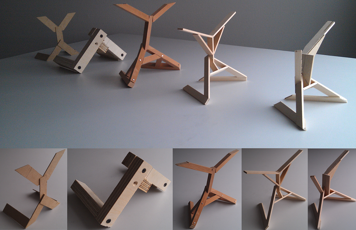
"The evolution of man"... as a sawhorse. Bigger Image Here
The process of translating a conceptual form into a functioning object with real-world dimensions was one that could only be figured out by hand (no amount of head-scratching in the virtual realm would amount to anything real, as I discovered after several futile attempts to visualize my real-world design with software). Failures were common, but so were discoveries. There were three major discoveries in the process of model-making that alone made the final product exactly what it became. The transformation between the first and second models was discovering how actual pieces of lumber might work and fit together as one structure. That between the second and third was unveiling a complete form, while discovering real-world balances and forces and the respective angles and bracing that might be necessary. There were a few minor discoveries between the third and fourth models, dealing more with balance, connections, and bracing, and perhaps a more realistic transformation into what a full scale product with dimensional lumber would look like. But the final major discovery came between the fourth and fifth models, in the form of a reconciliation of several issues I could not ignore from the fourth model.

In the fourth model (left), it was obvious I needed to do something about the "kneebone" connection. The joint in the fifth (right) seemed to be the best possible solution (and in the end at full scale, proved me right).

The most significant change from the fourth model (left) to the final mockup (right) came at the core. The struggle up to this point was figuring how to make a strong and secure connection between the upper and lower "body" of the form. On the left, the upper and lower bodies are separated from one another, and in my mind, there was simply no connection that could be made between them that would have made me feel comfortable with its integrity. It eventually dawned on me, for the purposes of strength and integrity, there should be no connection at all, but instead one solid piece, to which everything else attached is to, like the keel of a ship. To retain the shape I still wanted (better mimicking a human mid-section), I would later remove the forward half-portion of the "keel" piece (crossed out in the right image). Bigger Image Here

The final small-scale mockup. This is the model from which everything else at full scale would refer to and follow. I debated about attaching the "oblique" bracing (the supports for the "arm" pieces) to the "hip-and-thigh" area or to the core keel piece (in this image the left oblique is attached to the core, while the right is attached to the hip-and-thigh area). I was concered about lateral forces, figuring the keel piece may snap in half if strained enough from side to side. However, I decided to green-light the design for the left oblique, despite my concerns at the time (this decision presented problems later). The model here looks incomplete, but it was complete in my mind (it simply told me everything I would need to know at full scale). I was ready to finalize the design. Bigger Image Here

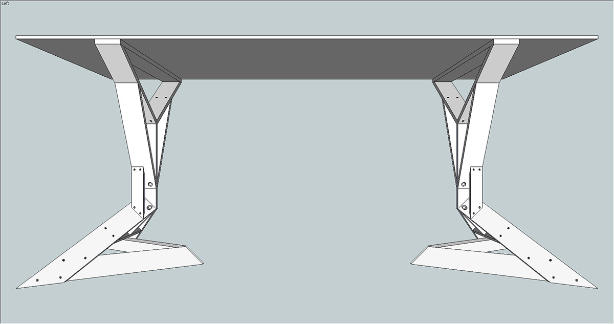
A last return to software made it final. After several failures and discoveries in the real world, it was now fairly easy to finalize a design and a visual representation of something that could be replicated at full scale, with few if any hiccups along the way. Bigger Image Here

The "hip" braces you see here were not actually part of the original final design. As I said before, the decision to attach the shoulder/oblique supports to the center spine (instead of the upper legs) was one that presented problems. I actually built my first full scale version without these braces, and it was clear that any lateral force would just snap the horse right in half. So I went back and added these hip braces to the model. In the end, they actually give the form a more "human" quality.

As you might have noticed by now, the final two horses at full scale do not have the same lower legs (one pair is shorter than the next). This was the result of a modification along the way. Here, concerned about the backward force causing the horse to "sit" back on its lower legs, I decided to lengthen the legs as much as possible to prevent the horse from toppling backward.
Time to build. Period.

A big confidence booster, seeing this sitting on the table in front of me.

I thought about every little thing for this design, right down to the hardware I would use. I wanted to use screws to fasten it together, so that it could be taken apart if necessary. I intended to use the plain black drywall screws you see here only temporarily, replacing them later with the silver screws you see in the upper left corner. However, I liked the contrast of the light aspen wood with the dark drywall screw so much, I decided to keep them.

This is how I originally wanted the horses to look (no hip bracing). I thought it gave a better-looking profile to the piece. However, as you can probably tell, it was just too vulnerable at its core, and would snap right in half with any shift of the weight it would be supporting. See that level at the bottom of the picture? To my utter surprise, this thing came out perfectly level at the top.

Each horse is made from about two 8 in. by 8 ft. pieces of aspen board (you can see an uncut, unwrapped piece sitting on the table next to the horse). They were each ripped into 4 in. wide pieces to give me enough material to work with.

Here's the completed prototype (the first of two horses). This picture felt really good when I took it.

Notice in this prototype the shorter lower legs and lack of hip bracing. These were the two major things I would address in building the final horse.

Here's a complete model, which I went back and finished after the project was completed. It includes all hardware and fasteners (screws, bolts, nuts, etc.), and all drill holes that were made. Bigger Image Here

Looking at this image, the hip braces actually provide more of an aesthetic purpose than I had intended. In addition to giving the structure integrity, they also act to "cover" the nuts and bolts underneath. That said, maybe I should have extended the back edges of the braces (following the profile of the back spine) to completely conceal all four bolts.

Top piece is exactly 3 ft. wide. Final dimensions for the whole piece: exactly 3 ft. tall by exactly 3 ft. wide by roughly 2 ft. deep (the prototype is exactly 18 inches deep, with its shorter lower legs).

Some of the toughest cuts that were made for this piece were those involved in the upper and lower legs (so that the horse would sit flush with the ground). Lots and lots of angles... and headaches by the end of the day.


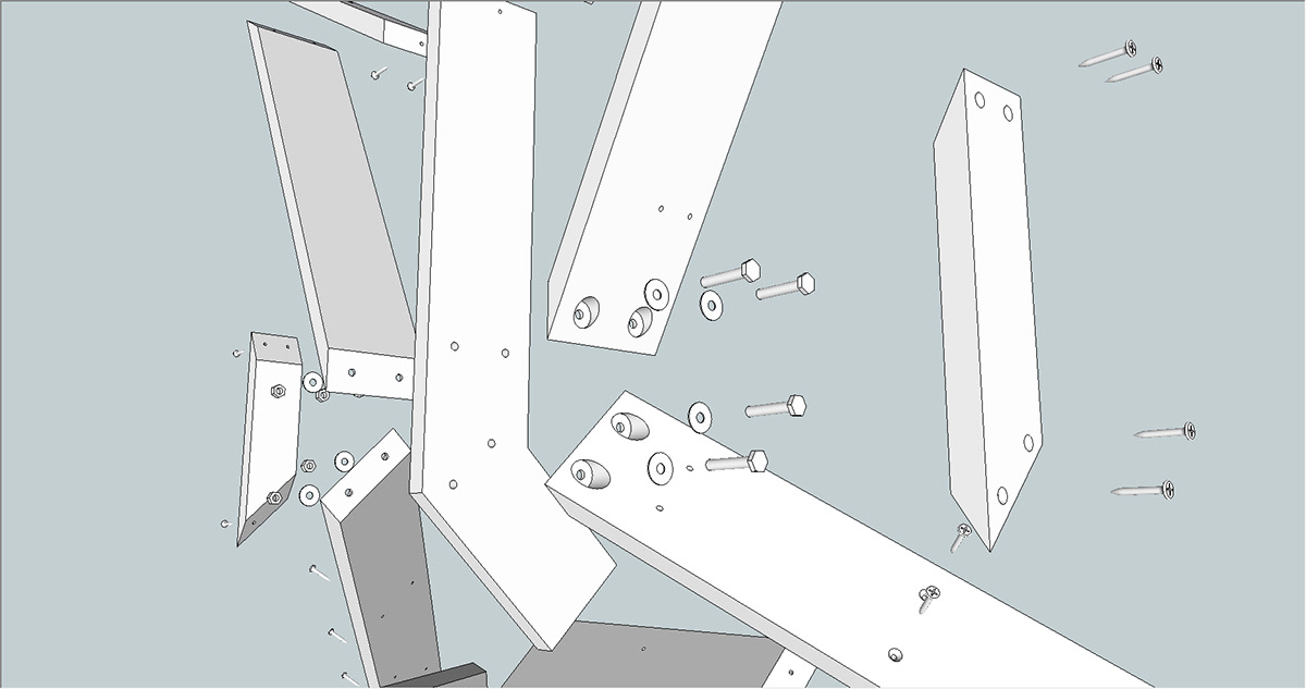
Here are some images of the model partly and completely disassembled. More complicated than it looked at first glance, huh? Bigger Image Here

In all: 13 boards, held together by 4 bolts, 4 nuts, 8 washers, and 34 screws. Bigger Image Here


All apart now...

Images like these make me wonder how the hell everything came out so perfectly. Bigger Image Here


It wasn't originally intended, but these sawhorses do actually stack together to save the user some space...keep your jokes to yourself.

Here they are, working together as a team. Bigger Image Here

For those of you who may have been doubting the strength of these sawhorses...this is for you. 185 lbs. plus a 50 lb. sheet of plywood... that'll do the job for any garage.

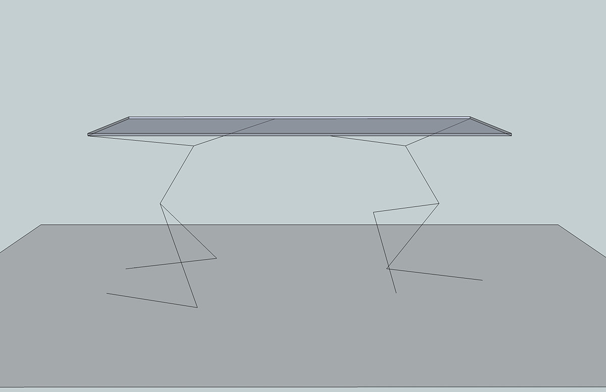
Again, the final product...this time supporting a fancy (and expensive) glass table. Bigger Image Here
